
CHAPTER 08
Building heat balance.
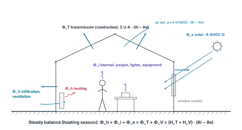
A building is a thermal system with heat inputs and outputs. Adding up the U-values of Chapter 07, the air that leaks through the envelope, the heat of people and equipment and the sun through the windows gives the heating power a building needs, and, with degree days, its heating energy over a season.
Steady state throughout; metric units; equations 8.1–8.8. The weather is the Ithaca TMYx file of Chapter 01, the irradiance on windows comes from Chapter 05. US (ASHRAE) and German (DIN V 4108-6, VDI 3807) conventions are given side by side.
StartISO 52016 · ASHRAE · DIN V 4108-6
Quantities and symbols
The symbols of Chapter 07 (Q, Φ, q, θ, U) continue. Four new quantities describe a whole building.
| Symbol | Quantity | German | Unit | Eq. |
|---|---|---|---|---|
| HT, HV, H | Transmission, ventilation and total heat loss coefficient | spezifischer Transmissions-, Lüftungswärmeverlust | W/K | 8.1–8.3 |
| n | Air change rate (ACH) | Luftwechselzahl | h⁻¹ | 8.3 |
| Φi, Φs, Φh | Internal gains, solar gains, heating power | interne, solare Wärmegewinne, Heizleistung | W | 8.1, 8.4 |
| SHGC · g | Solar heat gain coefficient · total solar energy transmittance | Gesamtenergiedurchlassgrad g | – | 8.4 |
| HDD · Gt | Heating degree days | Gradtagzahl | K·d | 8.5–8.6 |
| θb | Balance-point temperature | Heizgrenztemperatur | °C | 8.7 |
| η | Utilization factor of the gains | Ausnutzungsgrad | – | 8.8 |
GAINS = LOSSES · EQ. 8.1
The energy balance of a building
Indoors stays at a constant temperature only if what comes in equals what goes out. In winter the sun and the occupants supply part of the heat; the heating supplies the rest. In summer the balance runs the other way, and the surplus must be removed by ventilation or cooling.
- H = HT + HV is the building's heat loss per kelvin: one number that collects the whole envelope and its airtightness. The resistor analogy of Chapter 07 continues: the building is a set of conductances in parallel between the indoor and the outdoor node.
- For a design heat load (sizing the heating plant) take a cold design temperature, no sun and usually no internal gains: Φh = H · (θi − θe,design). For energy over a season, sum the balance over time (section 06).
Σ U·A + Σ ψ·l · EQ. 8.2
Transmission
Each element of the envelope conducts U·A watts per kelvin. Thermal bridges add their linear and point values (Chapter 07, section 07).
| Element | Construction | A m² | U W/(m²K) | U·A W/K |
|---|---|---|---|---|
| Roof | Timber rafters, 220 mm cellulose, wood-fiber board | 106 | 0.192 | 20.4 |
| Walls | 240 mm solid brick, 160 mm wood-fiber insulation, plaster | 140 | 0.233 | 32.6 |
| Windows | Double clear glazing (center of glass) | 24 | 2.72 | 65.3 |
| Floor | Treated as adiabatic in the lecture | 70 | – | – |
| HT | 270 | 118.3 |
- The windows are 9 % of the envelope area and 55 % of HT. In most buildings glazing, airtightness and junctions decide more than the last centimeters of wall insulation.
- A floor on the ground loses less than one to outside air because the ground is warmer than winter air and has a large resistance. Simple methods multiply U·A by a reduction factor (DIN V 4108-6: Fx ≈ 0.6 for a slab on grade); ISO 13370 and ASHRAE give detailed methods.
- The U-values of real windows include the frame and the glass edge (section 05); the center-of-glass value is optimistic.
ACH · BLOWER DOOR · EQ. 8.3
Infiltration and ventilation
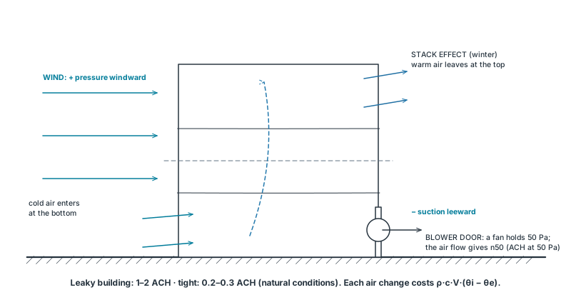
Every cubic meter of cold air that replaces warm indoor air must be heated. Infiltration is unwanted air leakage through cracks and joints, driven by wind and buoyancy; ventilation is the fresh air the occupants need. Both are counted the same way.
- Air change rate n · ACH
- Volume of air exchanged per hour divided by the room volume. Leaky existing buildings: 1–2 h⁻¹; tight new buildings: 0.2–0.3 h⁻¹ of infiltration (lecture frame 652). Hygienic fresh-air demand is about 25–30 m³/h per person, roughly 0.3–0.5 h⁻¹ in dwellings.
- Blower-door test · n50
- A fan holds the building at 50 Pa and measures the air flow (ISO 9972, ASTM E779). Requirements: Germany (GEG, DIN 4108-7) n50 ≤ 3.0 h⁻¹, or ≤ 1.5 h⁻¹ with a ventilation system; IECC in the US: ≤ 3 ACH50 in climate zones 3–8 (Ithaca: 6A); Passivhaus ≤ 0.6 h⁻¹. Under natural conditions roughly n ≈ n50 / 20.
- Heat recovery
- A balanced mechanical ventilation system with a heat exchanger returns 75–90 % of the heat of the exhaust air: HV × (1 − ηHR). Opening windows cannot.
Airtightness and ventilation are separate tasks: "build tight, ventilate right". Do not reduce the fresh air for hygiene and moisture to save heat (Lehrbuch der Bauphysik II 4.3); reduce the leakage and recover the heat instead.
PEOPLE · LIGHTS · EQUIPMENT
Internal gains
People, lights and appliances turn almost all the energy they use into heat inside the building. In winter this offsets heating; in offices and schools it is often the largest cooling load.
| Source | Value | Notes |
|---|---|---|
| Person, seated, 1 met | ≈ 100–110 W total | 1 met = 58 W/m² × 1.8 m² body surface; about 70 W sensible, the rest latent (moisture) |
| Person, walking, 2 met | ≈ 210 W | dancing 2.4–4.4 met: the party problem of section 07 |
| Lighting, LED office | 5–10 W/m² | older fluorescent 10–15 W/m² |
| Equipment, dwelling / office | 2 / 7 W/m² | average over the day (SIA 2024); peaks are much higher |
| Kettle · microwave · refrigerator | 1800 · 1300 · 150–600 W | while running; kettles also release ≈ 500 W of latent heat |
| Occupancy density | 48 m²/person bedroom · 17 m²/person office | schedules turn densities into hourly gains (SIA 2024) |
- German monthly methods use a mean internal gain of 5 W/m² of floor area for dwellings (DIN V 4108-6), about 22 kWh/(m²a) over a 185-day heating season.
- Only sensible heat raises the air temperature. Latent heat (evaporation from people, cooking, showers) adds moisture; it matters for dehumidification and cooling, not for the winter heat balance.
U · SHGC (g) · LOW-E · EQ. 8.4
Windows: heat loss and solar gain
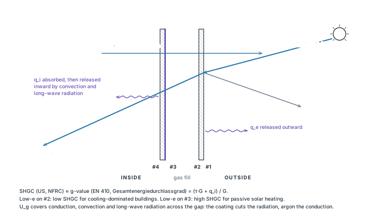
A window loses heat like a wall, only five to twenty times faster, and it lets the sun in. Two numbers describe it: the U-value for conduction, convection and long-wave radiation, and the solar heat gain coefficient for short-wave radiation.
| Glazing | Ug W/(m²K) | SHGC (g) | τvis |
|---|---|---|---|
| Single, clear 3 mm | 5.89 | 0.91 | 0.91 |
| Double, clear, 6 mm air | 2.72 | 0.76 | 0.81 |
| Double low-e, tinted, coating on #2 | 1.49 | 0.37 | 0.44 |
| Double low-e, coating on #3 | 1.51 | 0.65 | 0.77 |
| Triple low-e | 0.79 | 0.47 | 0.66 |
- Whole window Uw
- Uw = (Ug·Ag + Uf·Af + ψg·lg) / Aw (ISO 10077-1; Bauphysik Gl. 5.2). Frames: timber and PVC about 1.0–1.5, aluminum without a thermal break up to 4–6 W/(m²K); the spacer at the glass edge adds ψg ≈ 0.03–0.08 W/(m·K). US ratings (NFRC) give the whole-window U-factor and SHGC directly.
- SHGC and g
- Both are the share of incident solar radiation that ends up as heat in the room: transmitted plus the absorbed part released inward. The EN 410 g-value is usually quoted for the glass at normal incidence; NFRC SHGC for the whole window. Both fall at large angles of incidence (lecture frame 673).
- Low-e coatings
- A thin metal-oxide layer with ε ≈ 0.02–0.1 cuts the radiation across the gap (Chapter 07, Eq. 7.10). Argon or krypton reduce conduction. On surface #2 a selective coating also rejects solar infrared: low SHGC for cooling. On #3 it keeps a high SHGC for passive solar heating.
Is a window a heat loss or a heater? Over a heating season the answer depends on orientation and glazing. The drawing compares the conduction loss of 1 m² of glass with its solar gain for each month of the Ithaca file.
PER m² OF GLASS, WITH CURRENT VALUES
| Glazing | Ug | SHGC | South | East | West | North |
|---|
- From October to April a south window in Ithaca gains more than it loses with any glazing better than single glass; east and west roughly break even with double glazing; north windows lose heat with everything except triple low-e. These are upper bounds: frames, shading, dirt and unusable gains (below) reduce them.
- The tinted low-e glass (#2) improves U as much as the clear low-e (#3) but gives up about half of the solar gain: right for cooling-dominated buildings, wrong for passive solar heating.
- Not every gain is useful: on a sunny day in October the building may already be warm enough. Section 07 shows how the utilization factor accounts for that, and why it depends on thermal mass.
HDD · Gt20/15 · EQ. 8.5–8.6
Degree days and seasonal heating demand
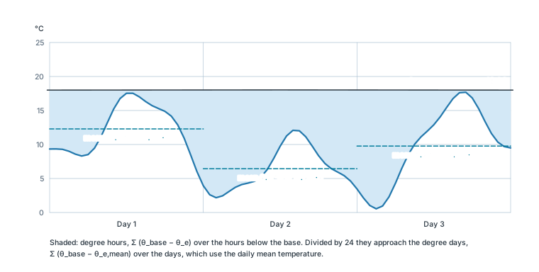
In steady state the heat loss is H × Δθ. Over a season Δθ changes every hour, but because the balance is linear we only need its sum: how much, and for how long, the outdoor temperature stayed below a base temperature. That sum is the degree-day number.
EQ. 8.5 WITH CURRENT VALUES
| Convention | Definition | Ithaca TMYx | Used for |
|---|---|---|---|
| US HDD, 65 °F (ASHRAE, NOAA) | Σ (18.3 − θe,mean)⁺ over all days | 3568 K·d | energy statistics, utilities, codes (climate zones) |
| Base 18 °C (lecture) | Σ (18 − θe,mean)⁺ | 3484 K·d | the lecture example |
| Germany Gt20/15 (VDI 3807) | Σ (20 − θe,mean) over days with θe,mean < 15 °C | 3881 K·d · 234 days | weather correction of metered consumption, energy certificates |
| Germany, reference climate (DIN V 4108-6) | Heating period of 185 days | – (Germany: 2900 K·d) | the simplified EnEV method below |
- The base is not the thermostat setting: gains supply the last few kelvin, so heating starts below the balance point θb (Eq. 8.7). A well-insulated house has a lower balance point and far fewer degree days.
- The lecture used 4150 K·d at 18 °C from a Syracuse weather file. The Ithaca TMYx file (built from 2009–2023) gives 3484 K·d at 18 °C; 4150 is reached only at a base near 20 °C. Always state the base, the convention and the weather file with a degree-day value.
- German practice combines degree days and gains in one line: Qh = 66 · (HT + HV) − 0.95 · (Qs + Qi) kWh/a, where 66 = 2.9 kK·d × 24 h × 0.95 / 1000 (EnEV 2002 annual method; Bauphysik Gl. 10.60).
- Cooling degree days are far less reliable: cooling depends on solar and internal gains and on humidity at least as much as on outdoor temperature (Szokolay). Use them only as an indicator, and hourly simulation for design.
- Heating energy is useful energy. The fuel or electricity delivered to the site is larger by the losses of the system (boiler efficiency η ≈ 0.9–0.95) or smaller with a heat pump (COP 2.5–4); primary energy adds the losses of producing and delivering it (lecture frame "Energy ≠ Energy").
WORKED EXAMPLE · PARTY PLANNING · EQ. 8.7–8.8
The house in Ithaca
The lecture house combines every flow of this chapter. Its transmission (section 02) and infiltration (section 03) give H; the outdoor temperature gives the heating power, the degree days its energy. The party problem asks the balance backwards: how many guests replace the heating?
The gains present most of the time lower the temperature at which heating must start:
EQ. 8.1–8.7 WITH CURRENT VALUES
Roof 106 m², walls 140 m², windows 24 m², floor 70 m² (adiabatic), volume 420 m³. Seasonal demand uses the degree days of the Ithaca file at the balance point of the residents' gains, without solar gains.
Useful gains and thermal mass
On mild, sunny days the gains exceed the losses and the surplus overheats the rooms instead of saving heating. Monthly methods (ISO 13790, DIN V 4108-6, DIN V 18599) multiply the gains by a utilization factor that depends on the gain-to-loss ratio γ and on the building's time constant τ = C/H (Chapter 07, Eq. 7.13):
- At γ = 0.5 a light building (τ = 8 h) uses 79 % of its gains, a heavy one (τ = 48 h) 97 %; at γ = 1 the values are 60 % and 80 %. Mass matters most where gains are large: passive solar houses, offices, spring and autumn.
- This is where transient behavior (Chapter 07, section 09) enters a steady method. For daily peaks and overheating, use an hourly simulation.
7 QUESTIONS · CALCULATION AND CONCEPT
Self-test
"New values" generates a new variant of a calculation. Each answer shows a worked solution.
EDITABLE VECTOR FILES
Figure files
Editable SVG files of every figure. Interactive drawings save their current state with "Save SVG".
- energy-flows.svg · Fig. 1 · Heat flows of a building
- infiltration.svg · Fig. 2 · Infiltration: wind, stack effect and the blower-door test
- glazing-shgc.svg · Fig. 3 · Solar heat gain coefficient (g-value) of double glazing
- degree-days.svg · Fig. 4 · Degree hours and degree days
SOURCES
Sources and model notes
- H.-M. Fischer, R. Jenisch, M. Stohrer et al., Lehrbuch der Bauphysik, 6th ed., Vieweg+Teubner, 2008. Part II Wärme: §4 (ventilation), §5.4 (windows), §10–11 (building heat demand, EnEV, DIN V 18599).0.34 · n · V, Uw, g-value and reduction factors, Gradtagzahl, Heizgrenztemperatur, utilization factor (Eq. 8.8).
- T. L. Bergman, A. S. Lavine, F. P. Incropera, D. P. DeWitt, Fundamentals of Heat and Mass Transfer, 6th ed., Wiley, 2007. §1.3 (conservation of energy), §12.5 (transmissivity), §13.2 (radiation exchange).Energy balance of a control volume; glazing and low-e physics.
- ASHRAE, Handbook — Fundamentals, SI edition: Ch. 9 (thermal comfort, metabolic rates), Ch. 14 (climatic design information, degree days), Ch. 15 (fenestration), Ch. 16 (ventilation and infiltration), Ch. 18 (load calculations).US conventions, HDD 65 °F, SHGC, internal gains.
- EN ISO 13790:2008 / EN ISO 52016-1:2017; DIN V 4108-6; DIN V 18599; VDI 3807-1.Monthly and hourly methods, utilization factor, heat capacity classes, Gt20/15.
- EN ISO 10077-1 (window Uw), EN 410 (g-value), NFRC 100/200 (U-factor, SHGC), EN ISO 9972 and ASTM E779 (blower door), EN ISO 13370 (ground).Section 02–05.
- S. V. Szokolay, Introduction to Architectural Science, 3rd ed., Routledge, 2014. §1.4 (heat flow, degree days); N. Lechner, Heating, Cooling, Lighting, 4th ed., Wiley, 2015.Degree-day method and the limits of cooling degree days.
- SIA Merkblatt 2024, Raumnutzungsdaten für Energie- und Gebäudetechnik.Occupancy densities and equipment gains.
- Ithaca Tompkins Rgnl AP TMYx (2009–2023), climate.onebuilding.org ↗Degree days and window balances; the dataset of Chapter 01.
- T. Dogan, ES1 lecture "Heat transfer, insulation materials", Cornell AAP, 2026, frames 583–684.Order of topics, the house in Ithaca and the party problem.
Model assumptions and precision
Steady state, one well-mixed zone at θi. Degree days use daily means of the 24 hourly values of the TMYx file. Window balances use center-of-glass U and SHGC, a vertical unshaded window, the isotropic sky of Chapter 05 with ground reflectance 0.2, and no angle dependence of the SHGC; gains are not reduced by a utilization factor. The house lab treats the floor as adiabatic, as in the lecture, and counts 100 W per person (sensible plus latent); seasonal demand uses the degree days at the balance point of the residents' and equipment gains and omits solar gains.