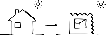
CHAPTER 03
Drawing shadows.
Shadows give a drawing depth. They show how far a balcony projects in an elevation, how tall a block is in a plan, and the shape of a building in a perspective. Constructed correctly, they also show where the sun falls. Hand construction uses the angles from Chapter 02: ALT and AZI for plans and three-dimensional views, and HSA and VSA for elevations and sections.
The constructions use the sun angles of Chapter 02, and equation numbers continue from it. Shadow length (Eq. 22) and the profile angle (Eq. 16–17) are derived in Chapter 04 and used here as given. Rays are parallel, so every shadow is built from the shadows of a few points joined by straight lines. Each figure can be saved as editable SVG. A short quiz closes the chapter.
StartWHAT TO CONSTRUCT
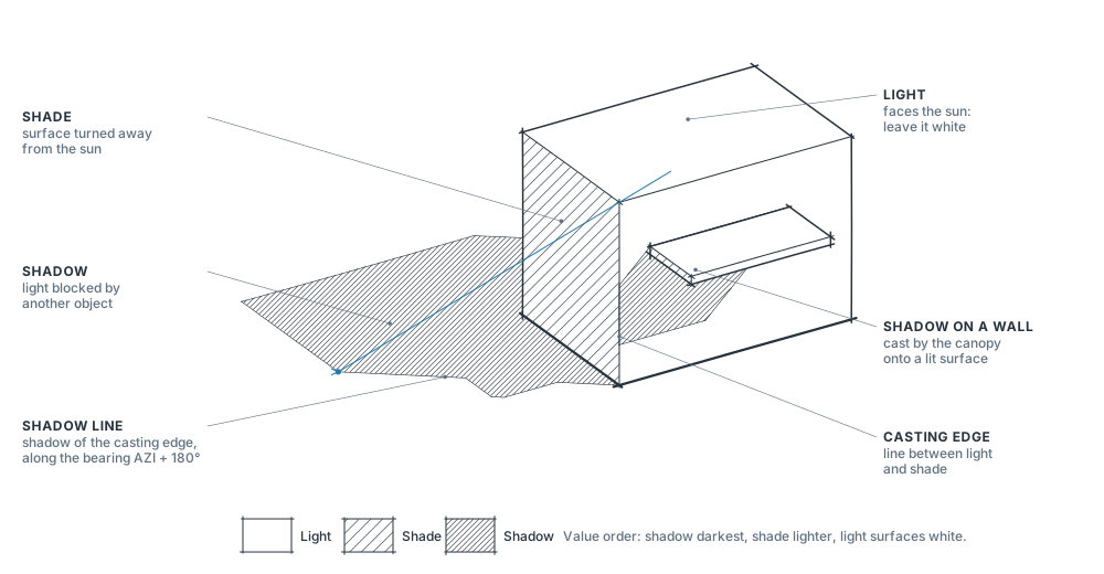
Light, shade and shadow
Rays are parallel. Every shadow is therefore built from the shadows of a few points, joined by straight lines. Construct lightly in pencil; ink only the result.
- Light
- A surface facing the sun. Leave it white.
- Shade
- A surface turned away from the sun (self-shading). It is darker than a lit surface but lighter than a shadow, because it still receives sky and reflected light.
- Shadow
- Part of a lit surface where the sun is blocked by another object or another part of the same building. A shadow can only fall on a surface that would otherwise be lit.
- Casting edge
- The edge between light and shade on the object. Only casting edges need to be constructed.
- Shadow line
- The shadow of a casting edge: the outline of the shadow.
FOUR RULES · EQ. 22
Casting shadows
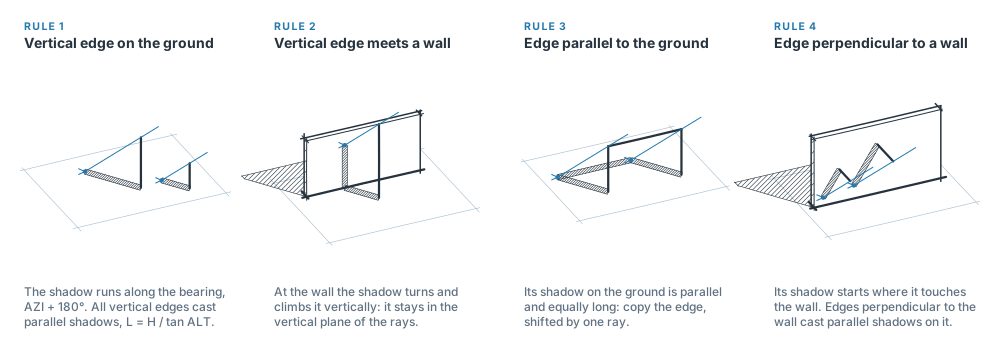
Four rules cover nearly all of an architectural drawing. With them, most shadow outlines are copied rather than constructed.
- Vertical edge on the ground. The shadow runs along the sun's bearing, AZI + 180°, with length L = H / tan ALT (Eq. 22). All vertical edges cast parallel shadows, and their lengths are proportional to their heights.
- Vertical edge meets a wall. The shadow turns at the base of the wall and climbs it vertically until it meets the ray through the top.
- Edge parallel to a surface. Its shadow on that surface is parallel to the edge and equally long. A roof edge's shadow on the ground is a copy of the edge, moved along one ray.
- Edge meeting a surface. Its shadow on that surface starts at the meeting point. Edges perpendicular to a wall all cast parallel shadows on it.
DESIGN STUDY OR PRESENTATION · EQ. 12
Real sun or 45° convention
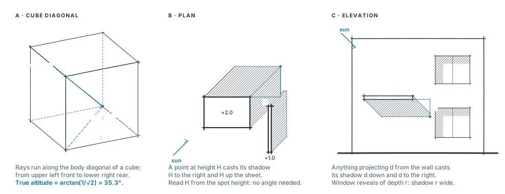
For a design study, use the real sun for the site, date and hour: ALT and AZI from Eq. 7–8, the sun-path diagram, or the sky hemisphere in Chapter 02. For presentation drawings with no particular time, architects use a convention. The rays run along the body diagonal of a cube, from upper left front to lower right rear. They appear at 45° in both plan and elevation, so no angle needs to be measured.
The 45° sun is a drawing device for showing depth. It belongs to no particular date or hour, and it says nothing about whether a space actually receives sun. When a drawing has to show sun access, overshadowing or the performance of a shading device, use the real sun and state the date and time on the sheet.
PLAN · SHADOW SCALE
Plans
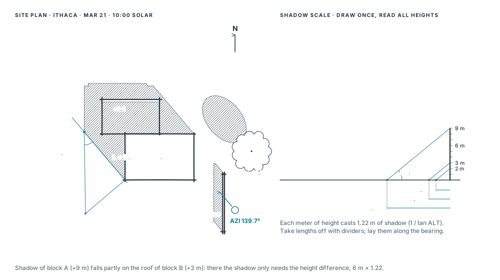
- Draw a north arrow and a sun arrow. The shadow bearing is AZI + 180°.
- Build a shadow scale at drawing scale: one vertical pole, marked in meters, and parallel rays at ALT. Every height's shadow length can then be read off with dividers. Alternatively, multiply heights by the factor 1 / tan ALT from the table below.
- From each corner of each roof outline, lay off L along the bearing.
- Join the tips with lines parallel to the roof edges (rule 3). Then draw the shadows of the vertical casting edges from the building corners to the tips (rule 1).
- Where a shadow falls on a lower roof, use only the height above that roof. Hatch the shadow and leave the roofs white.
| Date | 08:00 | 10:00 | 12:00 | 14:00 | 16:00 |
|---|---|---|---|---|---|
| Mar 21 · Sep 21 | 2.56 · 292° | 1.22 · 320° | 0.93 · 0° | 1.22 · 40° | 2.56 · 68° |
| Jun 21 | 1.31 · 271° | 0.61 · 298° | 0.34 · 0° | 0.61 · 62° | 1.31 · 89° |
| Dec 21 | 14.17 · 307° | 2.98 · 331° | 2.23 · 0° | 2.98 · 29° | 14.17 · 53° |
PLAN + SECTION → ELEVATION · EQ. 13
Elevations and sections
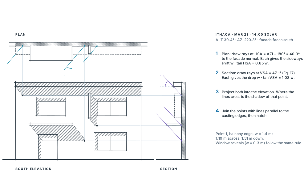
An elevation shows the facade straight on, so the sun appears in projection. In plan the rays make the horizontal shadow angle HSA with the facade normal. In section they make the vertical shadow angle VSA with the horizontal (Chapter 04, Section 03, Eq. 16–17). A point that projects a distance w in front of the wall casts its shadow sideways and down by:
Draw the plan above the elevation and a section beside it. Rays in the plan give the sideways shift and rays in the section give the drop. Project both into the elevation; where the projection lines cross is the shadow of that point. For the 45° convention, HSA = 45° and VSA = 45°, so both offsets equal w.
A section through an opening uses the same VSA ray. It shows how far down the facade an overhang's shadow reaches and where the sun patch falls on the floor inside (Lechner's sunbeam drawing). The interactive section in Chapter 04, Section 03 performs this construction for any date.
PARALLEL PROJECTION
Axonometric
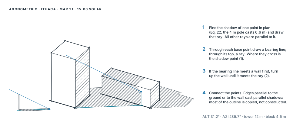
An axonometric keeps parallel lines parallel, so all rays are parallel and all bearing lines are parallel. Construct one shadow point properly: find its position in the plan with Eq. 22 and draw it in the axonometric. That fixes the direction of the ray and of the bearing line. Copy both directions with set squares for every other point.
VANISHING POINTS
Perspective
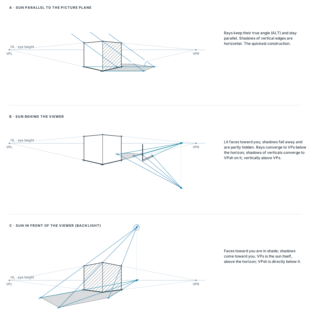
In a perspective, parallel lines converge. The sun's rays therefore converge to a vanishing point of their own, VPs. The shadows of vertical edges on the ground are horizontal lines, so they converge to a point on the horizon, VPsh, directly above or below VPs.
- Choose the sun's bearing by placing VPsh on the horizon.
- Choose the altitude by placing VPs on the vertical through VPsh: below the horizon when the sun is behind you, above it when the sun is in front of you. The farther VPs is from the horizon, the higher the sun and the shorter the shadows.
- For every vertical edge, draw a line from VPsh through its base and a line from VPs through its top. They cross at the shadow point.
- Shadows of horizontal edges on the ground run to the same vanishing point as the edge itself (rule 3).
When the sun is parallel to the picture plane, there are no sun vanishing points. Rays are drawn parallel at their true altitude and the shadows of vertical edges are horizontal. This is the fastest case for a sketch. With the sun behind you, the visible faces are lit and shadows fall away; with the sun in front, the visible faces are in shade and shadows come toward you.
FINE-LINER
Rendering with a fine-liner
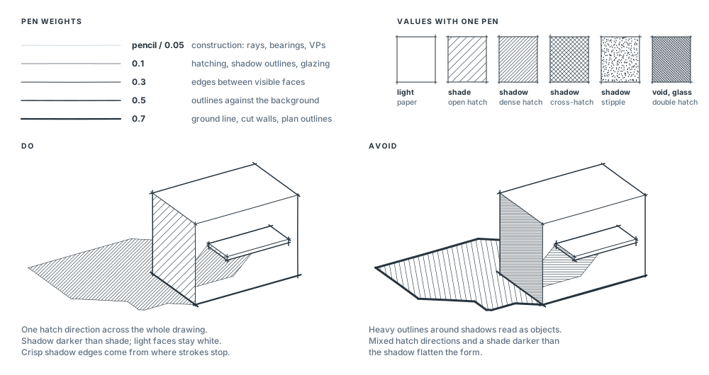
- Pencil first. Draw rays, bearing lines and vanishing points lightly in pencil or non-photo blue. Ink only the outlines and the hatching, then erase.
- Line hierarchy. 0.7 for the ground line and cut elements, 0.5 for outlines against the background, 0.3 for edges between visible faces, 0.1 for hatching.
- Value order. Shadow darkest, shade lighter, lit faces white. Hatch shade with the same pen at about twice the spacing used for shadow. Glass and deep voids can go darker still.
- One direction. Hatch every shadow on the sheet in one direction, usually 45°, at constant spacing (about 1 mm at 1:100). Mixed directions read as different materials.
- Edges from strokes. Start each stroke on the shadow edge so the edge reads crisply. If an outline is needed, use the 0.1 pen. A heavy outline makes the shadow read as an object.
Do all shadows of vertical edges point the same way? Are their lengths proportional to the heights? Does every object that stands on the ground have a shadow that starts at its base? Is every shadow on a lit surface, never on one in shade? Are the shadows of horizontal edges parallel to those edges? Is the date and time, or "45° convention", written on the drawing?
8 QUESTIONS · CONSTRUCTION AND CONVENTION
Mini quiz
Check the rules before you draw. Calculation questions take a number; "New values" generates a new variant. Each answer shows the construction or equation behind it.
Practice only. Responses stay in this browser.
EDITABLE VECTOR FILES
Figure files
Each figure is available as SVG with plain colors, named groups and live text, for editing in Illustrator, Inkscape or Keynote. The files are generated from the same code as the page (./reader generate:solar).
- sketch-vocabulary.svg · Fig. 1 · Light, shade and shadow · Hand drawing
- sketch-rules.svg · Fig. 2 · Four rules for casting shadows · Hand drawing
- sketch-convention.svg · Fig. 3 · The 45° convention · Hand drawing
- sketch-plan.svg · Fig. 4 · Plan shadows at a real date and time, with a shadow scale · Hand drawing
- sketch-elevation.svg · Fig. 5 · Elevation shadows from plan and section · Hand drawing
- sketch-axo.svg · Fig. 6 · Axonometric shadow construction · Hand drawing
- sketch-perspective.svg · Fig. 7 · Shadows in perspective · Hand drawing
- sketch-technique.svg · Fig. 8 · Fine-liner technique · Hand drawing
SOURCES
Sources and model notes
- S. V. Szokolay, Introduction to Architectural Science, 3rd ed., Routledge, 2014. Sections 1.3.1, 1.4.1; Method sheets M.1.1 (solar geometry), M.1.2 (stereographic charts, shadow-angle protractor).Abbreviations, Eq. 7–9, 16–18, 21; device masks.
- N. Lechner, Heating, Cooling, Lighting, 4th ed., Wiley, 2015. Chapter 6 (solar geometry), 9.5–9.9 (shading periods, overhangs).Solar window, sunbeam drawing, test dates, heliodons and sundials.
Model assumptions
The figures assume parallel rays, opaque objects and level ground. Shadows are computed in 3D from the sun position of Chapter 02 (Eq. 7–8) and projected into each view. The shadow-factor table uses Ithaca, 42.4° N, with geometric altitude (no refraction); entries are omitted when ALT is below 3°.
Continue to Chapter 04: Sun paths and shading ↗