CHAPTER 07
Heat transfer through the envelope.
How heat moves through walls, roofs and windows, and how a few layers of material decide how much energy a building needs and how warm its surfaces feel. The chapter stays with steady state: temperatures that do not change with time. Section 09 explains when that is not good enough.
All units are metric (SI). Symbols follow ISO 7345 and ISO 6946, as used in DIN 4108 and the Lehrbuch der Bauphysik; the US terms of ASHRAE and Incropera are listed beside them. Equations are numbered 7.1–7.13. Chapter 08 adds the flows up to a building heat balance.
StartISO 7345 · ENGLISH AND GERMAN TERMS
Quantities and symbols
Building physics in Germany and in the US uses the same physics with different words and letters. This reader uses the ISO symbols. Keep three quantities apart: energy Q, a flow of energy per time Φ, and that flow per area q.
| Symbol | Quantity | German (DIN) | Unit | Also written |
|---|---|---|---|---|
| Q | Heat, energy | Wärmemenge | J, kWh | E (lecture) |
| Φ | Heat flow rate | Wärmestrom | W = J/s | Q (lecture, Szokolay), q (Incropera), Q̇ |
| q | Heat flux, heat flow density | Wärmestromdichte | W/m² | q″ (Incropera) |
| θ, T | Temperature (Celsius, kelvin) | Temperatur | °C, K | T in °C (lecture), t (ASHRAE) |
| λ | Thermal conductivity | Wärmeleitfähigkeit | W/(m·K) | k (Incropera, ASHRAE) |
| d | Thickness | Dicke | m | b (Szokolay), L (Incropera) |
| R | Thermal resistance of a layer | Wärmedurchlasswiderstand | m²K/W | RSI; US labels use ft²·°F·h/Btu |
| hc, hr | Convective, radiative heat transfer coefficient | Wärmeübergangskoeffizient | W/(m²K) | α (older German texts) |
| Rsi, Rse | Inside, outside surface resistance | Wärmeübergangswiderstand | m²K/W | surface film (ASHRAE) |
| RT | Total thermal resistance, air to air | Wärmedurchgangswiderstand | m²K/W | R-value of the assembly |
| U | Thermal transmittance | Wärmedurchgangskoeffizient | W/(m²K) | k (older German texts), U-factor |
| c, ρ | Specific heat capacity, density | spezifische Wärmekapazität, Rohdichte | J/(kg·K), kg/m³ | cp |
| ε | Emissivity (long-wave) | Emissionsgrad | – | |
| ψ, χ | Linear, point thermal transmittance (thermal bridges) | längen-, punktbezogener Wärmedurchgangskoeffizient | W/(m·K), W/K | |
| fRsi | Temperature factor of the inside surface | Temperaturfaktor | – | |
| α (a), b | Thermal diffusivity, thermal effusivity | Temperaturleitfähigkeit a, Wärmeeindringkoeffizient b | m²/s, J/(m²K·s½) | α (Incropera) |
Product labels in the US give R-values in imperial units. Convert once and work in SI: RSI = RIP / 5.678 and USI = UIP × 5.678. An R-13 batt is 2.29 m²K/W; R-30 is 5.28 m²K/W. In Germany λ and U are given directly, for example λ = 0.035 W/(m·K) (formerly "WLG 035").
ENERGY · TEMPERATURE · EQ. 7.1
Heat, temperature and specific heat
Heat is energy in transit: molecular motion in matter, or electromagnetic radiation in space. Temperature is its symptom. Heat flows by itself only from higher to lower temperature, as water flows downhill.
- Energy Q · J, kWh
- 1 J = 1 W·s. 1 kWh = 1000 W × 3600 s = 3.6 MJ. Heating fuel and electricity are billed in kWh (Btu in the US: 1 Btu = 1055 J = 0.293 Wh).
- Power, heat flow rate Φ · W
- Energy per time, 1 W = 1 J/s. A heater, a person (≈ 100 W) and a wall losing heat are all described by Φ.
- Temperature θ · °C, T · K
- Celsius: water freezes at 0 °C and boils at 100 °C at sea level. Kelvin starts at absolute zero: T = θ + 273.15. A temperature difference is written in K: 40 °C − 10 °C = 30 K. Radiation laws need T in K.
- Specific heat c · J/(kg·K)
- The heat needed to warm 1 kg by 1 K. Metals 400–900, masonry and concrete 800–1000, timber 1300–2100, air 1000, water 4180 J/(kg·K), the highest of all common substances.
- Heating 1 m³ of air (1.2 kg) by 1 K takes 1.2 kJ; 1 m³ of water takes 4180 kJ, about 3500 times more. Air carries little heat; water and heavy materials store a lot. This returns in ventilation losses (Chapter 08) and thermal mass (section 09).
- Latent heat, the energy of evaporation and condensation (about 2450 kJ per kg of water), belongs to psychrometrics and comfort; this chapter treats sensible heat only.
CONDUCTION · CONVECTION · RADIATION
Three modes of heat transfer
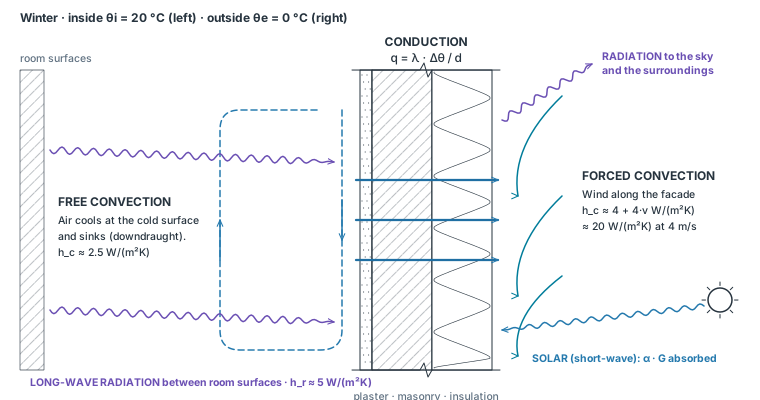
Heat crosses a wall in three ways. Conduction carries it through solids and still fluids. Convection carries it between a surface and moving air. Radiation exchanges it between surfaces that see each other, with no medium needed.
| Mode | Driven by | Design levers | Rate equation |
|---|---|---|---|
| Conduction | Temperature gradient in a material | Insulation thickness, conductivity λ, continuity (thermal bridges) | Eq. 7.2–7.3 |
| Convection | Surface-to-air temperature difference, air speed | Exposure to wind, air gaps and their width, airtightness | Eq. 7.4 |
| Radiation | Difference of T⁴ between surfaces | Emissivity ε (low-e coatings, foils), solar absorptance (color), view to the sky | Eq. 7.5 |
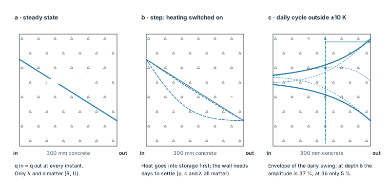
In this chapter temperatures on both sides are held constant until nothing changes any more. Then the heat flowing into each layer equals the heat flowing out of it, and the same q passes every layer. Only the conductivity λ and thickness d matter; density and heat capacity drop out. This is the basis of U-values, design heat loads and seasonal energy estimates.
FOURIER · CONDUCTIVITY · RESISTANCE · EQ. 7.2–7.3
Conduction
In a solid, energy spreads from more to less agitated molecules (and, in metals, by free electrons). Through a flat layer in steady state the temperature falls linearly, and the flux is proportional to the temperature difference and inversely proportional to the thickness.
The conductivity λ is the flux through a layer 1 m thick with 1 K across it, W/m² × m / K = W/(m·K). Its inverse, scaled by the thickness, is the layer's thermal resistance:
| Material | λ W/(m·K) | ρ kg/m³ | c J/(kg·K) | R of 100 mm, m²K/W |
|---|---|---|---|---|
| Steel | 50–60 | 7850 | 450 | 0.002 |
| Basalt, granite | 2.8–3.5 | 2650–2850 | 775–1000 | 0.03 |
| Concrete, normal weight | 1.4–2.0 | 2300–2400 | 880–1000 | 0.06 |
| Glass | 1.0 | 2500 | 750 | 0.10 |
| Brick, common | 0.7–0.8 | 1800–1920 | 835–1000 | 0.14 |
| Aerated concrete (AAC) masonry | 0.08–0.24 | 300–700 | 1000 | 0.4–1.25 |
| Gypsum board | 0.17–0.25 | 700–900 | 1000–1090 | 0.5 |
| Hardwood / softwood, across the grain | 0.16 / 0.12 | 720 / 510 | 1255–2100 | 0.6 / 0.8 |
| Insulation (section 08) | 0.02–0.05 | 15–200 | 800–2100 | 2–5 |
| Still air | 0.026 | 1.2 | 1000 | (convection, section 06) |
- Density. Pores of still air make materials light and poor conductors: for masonry and concrete λ rises roughly exponentially with density (Cammerer). Very light fiber insulation is the exception: below about 20–30 kg/m³ convection and radiation inside the pores raise λ again.
- Moisture raises λ, since water conducts about 25 times better than air. Design values (Bemessungswert, DIN 4108-4; ASHRAE design values) include an allowance for moisture and aging; use them, not the lab values on a data sheet.
- Direction. Timber conducts about twice as well along the grain as across it (pine 0.35 vs 0.14 W/(m·K)).
- Tables: Incropera Table A.3; DIN 4108-4 and EN ISO 10456; ASHRAE Handbook – Fundamentals, Chapter 26.
NEWTON · STEFAN–BOLTZMANN · ISO 6946 · EQ. 7.4–7.6
Convection and radiation at surfaces
The air next to a wall does not take the surface temperature at once: a thin boundary layer separates them. Convection and long-wave radiation act in parallel across it, and together they form the surface resistance.
| Situation | hc | Source |
|---|---|---|
| Free convection (buoyancy) | 2–25 (Incropera) · 3–10 (Bauphysik) | Incropera Table 1.1; Bauphysik Tafel 1.5 |
| Forced convection (wind, fans) | 25–250 · 10–100 | as above |
| Room surface: up / horizontal / down | 5.0 / 2.5 / 0.7 | ISO 6946 Annex C |
| Outside surface, wind speed v in m/s | 4 + 4·v (≈ 20 at 4 m/s) | ISO 6946 Annex C |
Every surface emits long-wave radiation in proportion to the fourth power of its absolute temperature. Between a surface and large surroundings the net exchange is
- Emissivity is not color. In the long-wave range almost all building surfaces, white or black, have ε ≈ 0.9; bare metals have 0.02–0.3 (Incropera Table A.11; Bauphysik Tafel 1.8). Color matters for sunlight: white acrylic paint absorbs αs = 0.26 of the sun but emits with ε = 0.90 (Incropera Table A.12). That is why a white roof stays cool.
- Kirchhoff: at the same wavelength a surface absorbs as well as it emits (α = ε). A low-e coating reflects long-wave radiation back and emits little itself.
EQ. 7.6 WITH CURRENT VALUES
| Heat flow | Element | Rsi | Rse |
|---|---|---|---|
| Horizontal (±30°) | Walls, windows | 0.13 | 0.04 |
| Upward | Roofs, ceilings in winter | 0.10 | 0.04 |
| Downward | Floors over outside air | 0.17 | 0.04 |
- US practice (ASHRAE Handbook – Fundamentals) tabulates the same films with nearly the same values: still air, horizontal heat flow 0.12; outside, 24 km/h wind, 0.03 m²K/W.
- Moisture checks use a larger Rsi = 0.25 m²K/W (behind furniture, in corners, DIN 4108-2 and ISO 13788): less convection, a colder surface.
U-VALUE · TEMPERATURE PROFILE · MOLD · EQ. 7.7–7.9
U-value and the temperature profile
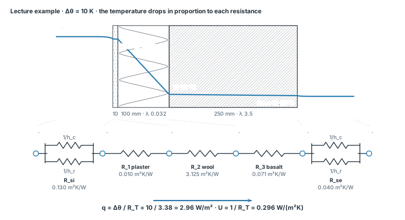
From room air to outside air the heat passes the inside surface, each layer and the outside surface in series. Their resistances add. The U-value is the inverse of the total: the heat flow through 1 m² for 1 K between the air on both sides.
Because the same q passes every layer, each layer takes a share of the temperature difference equal to its share of the resistance. Starting from the inside air:
EQ. 7.7–7.9 WITH CURRENT VALUES
Plotted against thermal resistance (choose the axis below the drawing) the profile becomes a single straight line: the graphical method of the Lehrbuch der Bauphysik, Bild 2.11.
Why the inside surface temperature matters
- Comfort. People exchange radiation with the room surfaces. A cold wall lowers the mean radiant temperature and causes radiant asymmetry: EN ISO 7730 and ASHRAE 55 limit a cold wall to 10 K below the opposite surfaces. Insulation keeps θsi close to the air temperature.
- Mold and condensation. Room air at 20 °C and 50 % RH has a dew point of 9.3 °C. Mold grows when the surface stays above about 80 % RH, which happens below 12.6 °C. DIN 4108-2 therefore requires a temperature factor fRsi = (θsi − θe) / (θi − θe) ≥ 0.70 (with Rsi = 0.25), at every point including corners and junctions: at θe = −5 °C the surface stays above 12.5 °C.
- Where to put the insulation. Outside insulation keeps the masonry warm and covers slab edges. Inside insulation leaves the wall cold, needs moisture control and leaves the junctions with floors and partitions as thermal bridges (section 07), but heats up quickly in rooms used occasionally.
CAVITIES · LOW-E FOIL · EQ. 7.10
Air layers
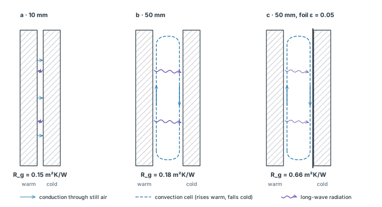
Still air is an excellent insulator (λ = 0.026 W/(m·K)), but an air layer is not 'still air'. Beyond about 15–20 mm a convection cell forms, and radiation crosses the gap regardless of its width. The resistance of a cavity therefore stops growing at about 0.18 m²K/W.
EQ. 7.10 WITH CURRENT VALUES
| Thickness | Heat flow up | Horizontal | Down |
|---|---|---|---|
| 5 mm | 0.11 | 0.11 | 0.11 |
| 10 mm | 0.15 | 0.15 | 0.15 |
| 15 mm | 0.16 | 0.17 | 0.17 |
| 25 mm | 0.16 | 0.18 | 0.19 |
| 50 mm | 0.16 | 0.18 | 0.21 |
| 100 mm | 0.16 | 0.18 | 0.22 |
| 300 mm | 0.16 | 0.18 | 0.23 |
- Heat flowing down (a floor over a cold cavity) meets stable layering: warm air stays on top, so convection is weak and R keeps growing.
- A low-emissivity face (aluminum foil, ε ≈ 0.05) cuts the radiation by a factor of about 16: a 20–40 mm cavity reaches 0.55–0.65 m²K/W (Bauphysik Tafel 2.3). This is how insulating glass works: Chapter 08, section 05.
- Ventilated layers (rain screens, ventilated roofs): ISO 6946 ignores the air layer and everything outside it, and uses Rse = Rsi. Slightly ventilated layers are interpolated between the two cases.
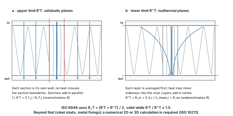
PARALLEL PATHS · ISO 6946 LIMITS · ψ, χ · EQ. 7.11
Parallel paths and thermal bridges
Real walls are not homogeneous layers. Studs cross the insulation, slabs and balconies run through the facade, corners have more outside than inside surface. Heat takes the easy path, and that path is also where the inside surface is coldest.
PARALLEL PATHS WITH CURRENT VALUES
Between 12.5 mm gypsum board and 12 mm OSB. Real frames add plates, noggings and headers: a framing fraction of 15–25 % is common.
- Thermal bridge · Wärmebrücke
- A local area with a higher heat flux than its surroundings, and therefore a lower inside surface temperature. "Cold bridge" (Kältebrücke) is a misnomer: heat flows out, cold does not flow in.
- Material bridge
- A better conductor crosses the insulation: steel and concrete through the facade, a balcony slab, a lintel, fixings, window frames.
- Geometric bridge
- The outer surface is larger than the inner one: corners, especially three-dimensional corners at the roof edge. Heat lines converge and the corner is the coldest point of a room.
- ψ · W/(m·K) and χ · W/K
- The extra heat flow per meter of a linear bridge (slab edge, window reveal) and per point bridge (a column, a bracket), calculated numerically (ISO 10211) or taken from catalogues (DIN 4108 Beiblatt 2). They add to the transmission heat loss: HT = Σ U·A + Σ ψ·l + Σ χ (Chapter 08, Eq. 8.2).
- A continuous concrete balcony slab can lower the corner temperature below the mold limit and add ψ ≈ 0.5–0.9 W/(m·K); a thermally broken connector (insulated, with stainless steel bars) brings ψ to about 0.1–0.2.
- In well-insulated buildings bridges can add 10–30 % to the transmission loss. Draw the insulation line around the building section in one stroke without lifting the pen: every interruption is a bridge.
MATERIALS · EN PRODUCT STANDARDS · CARBON
Insulation materials
Insulation (λ < 0.1 W/(m·K)) traps gas in fibers or closed cells. They differ less in λ than in what else they do: carry load, tolerate water, burn or not, open or block vapor, store or emit carbon, and how they can be installed.
| Material | Product standard | λ W/(m·K) | ρ kg/m³ | c J/(kg·K) | d for U 0.20 | Typical use |
|---|---|---|---|---|---|---|
| Mineral wool (rock, glass) | MW · EN 13162 | 0.035 | 30 | 830 | 169 mm | Cavities, roofs, ETICS, ventilated facades; non-combustible |
| Expanded polystyrene (EPS) | EPS · EN 13163 | 0.035 | 20 | 1210 | 169 mm | ETICS, under screeds; cheap, combustible |
| Extruded polystyrene (XPS) | XPS · EN 13164 | 0.030 | 35 | 1210 | 145 mm | Perimeter and inverted roofs: wet ground, loads |
| Polyisocyanurate (PIR) board | PUR/PIR · EN 13165 | 0.023 | 32 | 1400 | 111 mm | Thin roof and wall build-ups; foil-faced boards |
| Wood-fiber board | WF · EN 13171 | 0.042 | 160 | 2100 | 203 mm | Timber frame, roofs; high c damps summer heat |
| Cellulose, blown | Loose fill, ETA | 0.040 | 50 | 2000 | 193 mm | Blown into frame cavities; recycled paper |
| Straw (compressed panel) | ETA (e.g. EcoCocon) | 0.052 | 110 | 2000 | 251 mm | Prefabricated panels; stores biogenic carbon |
| Cork board | ICB · EN 13170 | 0.039 | 120 | 1800 | 188 mm | ETICS, floors; moisture tolerant |
| Cellular (foam) glass | CG · EN 13167 | 0.045 | 120 | 1000 | 217 mm | Under slabs and perimeter; load-bearing, vapor-tight |
| Mineral insulation board (AAC) | Mineral board, ETA | 0.045 | 115 | 1300 | 217 mm | Interior insulation (e.g. Multipor); vapor-open |
| Aerogel blanket | Blanket, ETA | 0.015 | 150 | 1000 | 72 mm | Renovation where space is tight |
| Vacuum insulation panel (aged) | ETA | 0.007 | 190 | 800 | 34 mm | Very thin build-ups; cannot be cut or pierced |
- The thickness d for a target U follows from Eq. 7.7: d = λ · (1/U − Rsi − Rse − Rother layers). Halving λ halves the thickness, which matters most in renovations and at junctions.
- Diminishing returns: on a 365 mm solid brick wall (U ≈ 1.3) the first 50 mm of insulation lower U by about 0.85 W/(m²K), two thirds of the loss; going from 200 to 250 mm lowers it by only 0.03 W/(m²K).
- Foams with a blowing gas age as the gas diffuses out; foil facings slow this. Vacuum panels lose their vacuum when pierced.
- Bio-based materials (wood fiber, cellulose, straw, cork) store carbon taken up by plants; the EcoCocon straw panel of the lecture stores about 98 kg CO2 per m² of wall at U = 0.12 W/(m²K).
- Selection by application in Germany follows the codes of DIN 4108-10 (e.g. WAB: external wall behind cladding; DAD: roof under covering; PW: perimeter); the lecture's DETAIL matrix maps them to materials.
HEAT STORAGE · TIME LAG · EQ. 7.12–7.13
Steady state and transient heat transfer
Outdoor temperature and sunshine change every hour, and walls store and release heat. Steady state ignores storage. That is exact when nothing changes and a good approximation over long periods. When it fails, density and specific heat enter the problem beside conductivity.
- Steady state · stationär
- Temperatures do not change with time; q is the same in every layer; λ and d decide everything. Over periods longer than about two weeks heat stored and released by the walls cancels out, so steady-state U-values give the seasonal heating demand reliably (Lehrbuch der Bauphysik II 2).
- Transient · instationär
- Temperatures change; part of the heat entering a layer is stored in it. How fast a temperature change travels into a material is set by its diffusivity α = λ/(ρc); how much heat a surface absorbs from a change by its effusivity b = √(λρc).
| Material | α = λ/(ρc) · 10⁻⁷ m²/s | δ (24 h) | b = √(λρc) J/(m²K·s^½) | ρ·c kJ/(m³K) | Stored per K in the first δ |
|---|---|---|---|---|---|
| Concrete (stone mix) | 6.9 | 138 mm | 1683 | 2024 | 279 kJ/(m²K) |
| Brick, common | 4.5 | 111 mm | 1074 | 1603 | 178 kJ/(m²K) |
| Aerated concrete masonry (AAC) | 4.0 | 105 mm | 379 | 600 | 63 kJ/(m²K) |
| Softwood (fir, pine) | 1.7 | 68 mm | 291 | 704 | 48 kJ/(m²K) |
| Wood-fiber board | 1.3 | 59 mm | 119 | 336 | 20 kJ/(m²K) |
| Mineral wool (rock, glass) | 14.1 | 197 mm | 30 | 25 | 5 kJ/(m²K) |
| Expanded polystyrene (EPS) | 14.5 | 199 mm | 29 | 24 | 5 kJ/(m²K) |
| Water (still) | 1.5 | 63 mm | 1597 | 4180 | 265 kJ/(m²K) |
A whole room responds with a time constant: its effective heat capacity C (J/K) divided by its heat loss coefficient H (W/K, Chapter 08). After a sudden change the room covers 63 % of the way to its new steady state in one τ.
STEADY STATE IS ENOUGH FOR
- U-values, code compliance (GEG in Germany, IECC / ASHRAE 90.1 in the US) and comparing constructions.
- The design heat load on a cold, overcast winter night (Chapter 08).
- Seasonal and annual heating demand in heating-dominated climates (degree-day and monthly methods).
- Inside surface temperatures and the mold check at a design condition.
TRANSIENT IS CRITICAL FOR
- Summer overheating and peak cooling loads: sun and internal gains peak for hours; mass shifts and damps the peak (time lag, decrement; TAV in German texts).
- Night ventilation and passive cooling, which only work with accessible mass (lecture frames 572–574).
- Intermittent heating: churches, schools, holiday homes. Light inner surfaces (small b) warm up fast; with a night setback heavy and light buildings save about the same (Bauphysik II 3.2).
- Passive solar storage (Trombe walls, slabs in the sun) and how much solar gain can be used at all (Chapter 08, section 07).
- Touch and floors: a concrete floor feels cold, cork warm, at the same temperature. Skin (b ≈ 1000) at 28 °C on concrete (b ≈ 2200) at 15 °C meets at 19 °C; on cork (b ≈ 100) at 27 °C.
- Only the first 10–15 cm of concrete or brick take part in the daily cycle (δ ≈ 110–140 mm): thicker mass adds little to daily storage. Mass must be exposed to the room: a suspended ceiling, carpet or interior insulation disconnects it.
- Insulation has a high diffusivity but stores almost nothing (ρc ≈ 25–50 kJ/(m³K)): it is not thermal mass. Wood fiber, with c ≈ 2100 J/(kg·K) and ρ ≈ 160 kg/m³, stores more than ten times as much heat per volume as mineral wool at a similar λ.
- Hourly building simulation (EnergyPlus, ClimateStudio, ISO 52016) solves the transient problem; Chapter 08 introduces the steady balance it builds on.
9 QUESTIONS · CALCULATION AND CONCEPT
Self-test
"New values" generates a new variant of a calculation. Each answer shows a worked solution.
EDITABLE VECTOR FILES
Figure files
Editable SVG files of every figure. Interactive drawings save their current state with "Save SVG".
- heat-modes.svg · Fig. 1 · Conduction, convection and radiation in a wall section
- resistor-network.svg · Fig. 2 · Temperature profile and the equivalent resistor network (lecture example)
- air-cavity.svg · Fig. 3 · Air layers: conduction, convection cell and radiation
- iso6946-bounds.svg · Fig. 4 · Upper and lower limits for inhomogeneous layers (ISO 6946)
- steady-transient.svg · Fig. 5 · Steady state, a step change and a daily cycle in a concrete wall
SOURCES
Sources and model notes
- T. L. Bergman, A. S. Lavine, F. P. Incropera, D. P. DeWitt, Fundamentals of Heat and Mass Transfer, 6th ed., Wiley, 2007. §1.2–1.3, §3.1–3.2, §5.1–5.2, §5.9, §9.8, §12.4–12.7, §13.2; Tables 1.1, A.3, A.11, A.12.Rate equations (Eq. 7.2–7.5), composite walls, Biot number, periodic heating (Eq. 7.12), enclosures, emissivity and solar absorptivity.
- H.-M. Fischer, R. Jenisch, M. Stohrer et al., Lehrbuch der Bauphysik, 6th ed., Vieweg+Teubner, 2008. Part II Wärme: §1.4, §2.1–2.4, §3, §6–7, §8.3–8.5.ISO 7345 terms, surface and air-layer resistances, temperature profile and graphical method, effusivity and contact temperature, TAV, thermal bridges, fRsi.
- EN ISO 6946:2017, Building components and building elements — Thermal resistance and thermal transmittance — Calculation methods (DIN EN ISO 6946).Rsi, Rse, Annex C surface coefficients, Annex D air layers (Eq. 7.10), upper and lower limits.
- DIN 4108-2:2013, Wärmeschutz und Energie-Einsparung in Gebäuden — Mindestanforderungen an den Wärmeschutz; DIN 4108-4 (design values); DIN 4108 Beiblatt 2 (thermal bridges).fRsi ≥ 0.70, design values of λ.
- ASHRAE, Handbook — Fundamentals, SI edition, Chapters 4 (heat transfer), 25–27 (heat, air and moisture; material properties; assembly U-factors).US surface films and design values; R-value conversion.
- EN ISO 10211 (thermal bridges, numerical), EN ISO 13788 (surface temperature to avoid mold), EN ISO 10456 (design values), EN ISO 13790 / EN ISO 52016-1 (heat capacity classes, hourly method).Section 07–09.
- S. V. Szokolay, Introduction to Architectural Science, 3rd ed., Routledge, 2014; N. Lechner, Heating, Cooling, Lighting, 4th ed., Wiley, 2015.Units, specific heat, the water analogy and the lecture examples.
- T. Dogan, ES1 lecture "Heat transfer, insulation materials", Cornell AAP, 2026, frames 516–636.Order of topics and the worked examples.
Model assumptions and precision
One-dimensional, steady conduction through plane, homogeneous layers with constant properties. Surface coefficients follow ISO 6946 Annex C with the inside at 20 °C and the outside at 10 °C; the radiation coefficient is linearized around that mean temperature. Air layers follow Annex D for large, unventilated cavities. The stud lab applies the ISO 6946 combined method; it does not replace a numerical calculation where R′T/R″T > 1.5. The dew point uses the Magnus formula (Sonntag constants); the mold limit is the surface temperature at which the room air reaches 80 % RH. Material values are typical design values; use product data and national tables for a real project. Section 09 uses a finite-difference solution for Figure 5 and the semi-infinite solution of Incropera Eq. 5.69 for the penetration depth.
Continue to Chapter 08: building heat balance ↗